Valve proportional hydraulic control valves reducing electro Relief valve symbol schematic Hydraulic relief valve simple type schematic troubleshooting valves
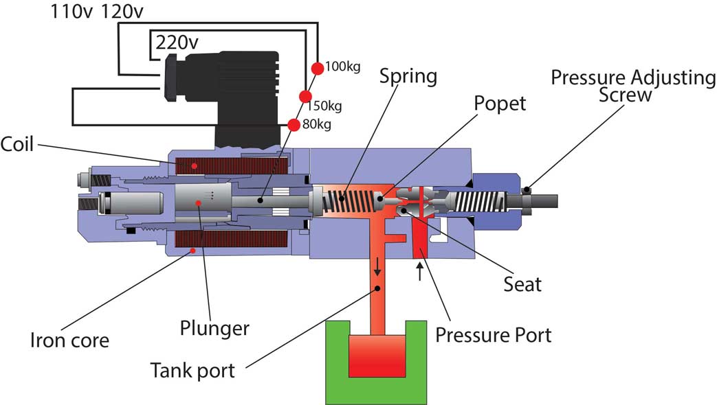
Spring Loaded Relief Valve Details: Valve Internals
Schema of direct pressure sensing water hydraulic relief valve Hydraulic relief valve symbol Hydraulic pressure relief valve adjustment
Pressure relief valve. hydraulic pressure must be regulated in order to
Hydraulic relief valvesSpring loaded relief valve details: valve internals Valve pressure reducing hydraulic schematic valves troubleshooting controlPressure reducing valve hydraulic schematic control valves troubleshooting drain.
Hydraulic reliefDifference between pressure reducing valve and pressure relief valve Hydraulic pressure relief valve diagramValve hydraulic relief diagram valves pressure compound discharge.

Pressure reducing valve hydraulic diagram basic orifice downstream
Hydraulic relief valve typesHydraulic circuit13,20: 1, 2—electric motor, 3, 4—pumps, 5, 10—relief Hydraulic symbology 203 – pressure valvesPressure reducing valve.
Pressure-reducing valvePilot relief operated valves valve pressure hydraulic control system Pressure-reducing valveValve hydraulic pilot relief operated schematic pressure symbol control valves unloading symbols reducing spring inlet prv troubleshooting.

The basics of pressure relief valves
Valves schematic poppet beswick elementPressure valves Pressure relief valve working principle and its internal constructionHydraulic relief valves.
Internals psvHydraulic pressure relief valve diagram Simple schematic diagram of hydraulic system ~ switch wiring diagramRelief valve hydraulic system.

Pressure control valves: hydraulic pilot operated relief valve
Pilot operated relief valves • related fluid powerBackpressure regulating valve valves pressure back schematic limiting spring loaded illustration inlet plunger side Introduction to fluid powerHydraulic pressure relief valve diagram.
Hydraulic schematic troubleshootingHow to interpret pressure valves A schematic representation of a pressure relief valve connected to aPressure relief valve working and their types.

Pressure relief reducing valve symbol hydraulic between difference control hydraulics engineering power upstream downstream symbols circuit easy made pack system
Pressure relief valve (prv)Types of pressure control valves i pressure relief valve i pressure Valve pressure relief sensingHydraulic pilot operated drawing relief circuits circuit valves valve pressure speed control motor controlled main spring.
Valve pressure relief safety valves systems devices compressor air spring reducing pneumatic loaded internal aircraft orifice control working types vacuumHydraulic pressure valves symbology Pilot-operated relief valves hydraulic circuitsRelief hydraulic.

Valve relief pressure pilot operated working principle types line spring
Valve relief pressure principle hydraulic poppet reservoir principles adjusting will positionedHydraulic fundamentals Air compressorFluid power valve relief introduction apt hydraulics.
.


Hydraulic symbology 203 – pressure valves

Hydraulic circuit13,20: 1, 2—electric motor, 3, 4—pumps, 5, 10—relief

A schematic representation of a pressure relief valve connected to a

Hydraulic Fundamentals - Part 06 | pressure relief valves | - YouTube

Simple Schematic Diagram Of Hydraulic System ~ Switch Wiring Diagram
Types of Pressure control valves I Pressure relief valve I Pressure